1 Introduction
With the in-depth study of the rapid development of power electronics technology and high-voltage inverter technology, high-voltage power converter is increasingly widely used in compressors, pumps, fans and other mechanical equipment power drive systems, high-voltage power inverter its superior performance and good energy-saving effect, making it more and more popular, showing its emerging market prospects. However, the current high-voltage power converter are still inadequate, especially in the pre-charge technology, still needs further improvement in order to make the performance and the results of high-voltage power converter for the better [1-4].
2 The current lack of high-voltage power converter in the pre-charging technology exists
2.1 Rectifier transformer phase shift exists insufficient
The current high-voltage power inverter at power control, generally in phase-shifting transformer rectifier is no low-pressure pre-charge circuit, and therefore must be set in the high-voltage circuits switching devices and limiting element, so that the power-on process becomes complicated, and frequently subjected to electric shocks on the current, high-voltage power converter is very prone to failure, thus greatly reducing the reliability of the system [4-6].
2.2 Insufficient power unit exists
Since the high-voltage power inverter to run every time you boot, you need to first create a DC bus voltage. And general high-voltage power converter are cascaded, each phase voltage outputs are connected in series by a plurality of power cells constitute However, while each individual unit includes a plurality of capacitive, so the system at power-on a huge impact on the input current is effectively suppressed necessary. At this point even more urgent need for a pre-charge circuit has a good performance to reduce the presence of the impact of current, so the impact on the system and the grid is reduced to a reasonable range, thereby improving system reliability, while reducing to Power interference.

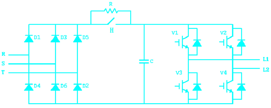
Power unit structure diagram of a conventional high-voltage power converter
The current high-voltage power converter cascade is mainly the more traditional pre-charge circuit from the power resistors and relays constituted shown in Figure 1. The problem is that its existence: the high cost of high-pressure type of relay, larger, will have a greater noise and mechanical contacts when the action is easy to bad;, but also because it is not prone to accurately cut the current limiting resistor and cause a fire the risk that affects the reliability and safety of the entire system [7-10].
3 The new high-voltage power converter design
3.1 The overall design of the new system block diagram
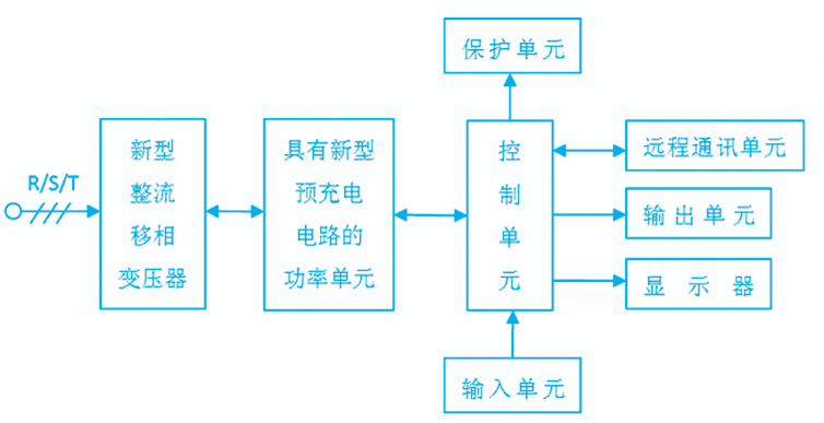
Its overall design of the new system block diagram shown in Figure 2, a new high-voltage power rectifier drive by the new phase-shifting transformer, with new pre-charge circuit power unit, control unit, an input unit, monitor, output unit, remote communications unit and protection unit.

The overall design of the new system block diagram in Figure 2
3.2 The new design of phase-shifting transformer rectifier
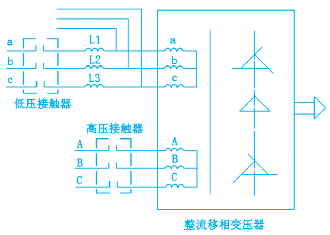
In order to solve the problem of the current phase-shifting transformer rectifier exist, the paper made its following improvements: shown in Figure 3, in the new phase-shifting transformer rectifier existing high voltage winding a, b, c, and high-voltage contactors outside in addition to, added a new low voltage coil group a, b, c, and the low voltage coil and contacts in series with the low-pressure limiting element l1, l2, l3 precharge circuit component.

The new rectifier Figure 3 improved phase-shifting transformer
3.3 Improve the design of the power unit
Because simply phase-shifting transformer rectifier to improve the overall effectiveness of the inverter precharge is not the best, it is the use of phase-shifting transformer rectifier inherent to suppress the leakage current of each power unit electric shock when its high-voltage power phase shift is difficult to accurately calculate the leakage inductance of the transformer and regulator, which will result in practical applications, it is difficult to achieve an effective suppression of the impact of current results. This in order to better pre-charge, you also need to improve the design of its power unit.
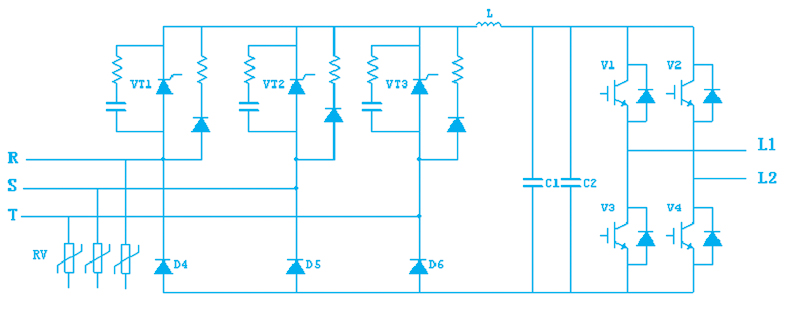
In this paper, the power unit for the current shortage exists, its made the following improvements: shown in Figure 4, the diode bridge rectifier is used in the transformation of the current half-controlled three-phase bridge rectifier circuit, while at the input to increase the input overvoltage absorption circuit, the middle section is designed smoothing inductance l, high-frequency capacitance DC bus capacitors c1 and c2.

Figure 4 The improved structure of the power unit
Wherein the input terminal input overvoltage absorption circuit is composed of three varistors rv with star connection are interconnected;-phase half-controlled bridge rectifier circuit consists of three identical branches connected in parallel with each other, and each branch routing a thyristor and a diode (eg vt1 and d4), each of the left have rc snubber circuit in parallel thyristors, the rc snubber circuit consists of a capacitor and a resistor, each thyristor has the right to charge the parallel branch, the branch of the charge consisting of a diode and a resistor; intermediate section of the high frequency inductor l smoothing capacitor c1, and two parallel composition and the DC bus capacitor c2, its rear portion to maintain the current constant.
4 Improved beneficial effect of the new design
Analysis shows that theoretically, to improve the design phase shifting transformer rectifier will make the new high-voltage electric power inverter only on the system each time, the first low-voltage contactor is turned, for the first precharge power unit, etc. after the completion of the power unit filter capacitor charging process, then disconnect the low voltage contactor precharge circuit resection, and finally the high-voltage switch is closed, the system into normal operation. So that the precharge circuit can effectively reduce the impact of the inverter and the power grid. In addition, due to the work of the pre-charge circuit for use in low-voltage circuits, no high voltage switch, the power supply circuit has been simplified, with the commissioning of low voltage can be, to debug brought great convenience. It also makes running the program be simplified so that it has a good economy and maneuverability.
In addition, the power unit to improve the design, the use of semi-controlled three-phase bridge rectifier, through the pre-charge circuit so that the power unit is pre-charged to the DC bus rated voltage value, which can avoid the power bus capacitance due to bear high di / dt value it premature failure; while avoiding its rectifier diode due to withstand high di / dt values and cause damage, causing the entire unit failure and quit. Therefore, to improve the design of the power unit increases the reliability and safety of the system, while its relatively low cost, ease of wide application. Visible, the improved new high-voltage power converter technology in pre-charge will have better control effect.
5 Conclusion
Firstly, in view of the current lack of high-voltage power converter precharge technically exist, its in-depth analysis. Then aspects, from the overall design of the system, a new phase rectifier transformers, power units, etc. while working, put forward specific improvement program, designed a new high-voltage power inverter. The new high-voltage power converter with better pre-charge function without high pressure switch, low pressure to debug, easy debugging, good maneuverability, has a better system reliability and safety, low cost, ease of wide application.
About the Author
Jiang Xuefeng (1987 -) male Nanjing graduate, Aviation Research Laboratory of Power Air Tech University of Aeronautics and Astronautics of power electronics and electric drive motor and electrical
Huang Wenxin (1966 -) Professor male Nanjing Aviation Air Power Key Laboratory of Science and Technology, Beihang University, doctoral tutor, the main research directions for power electronics and electric drive motor and electrical
References
[1] Branch of China Electrical Equipment Industrial Association, the inverter voltage inverter Application Manual [m] Beijing: Mechanical Industry Press, 2009
. [2] Zhang choose positive, Zhang Jinyuan Application technology and practice drive [m] Beijing: China Electric Power Press, 2009
. [3] Li Yan, Liao Yikui, Wang and other graphic converter application [m] Beijing: China Electric Power Press, 2009
. [4] Li Zheng. Hypertension inverter technology trends [j]. Shanghai Energy Conservation, 2009.
[5] Zhoude Xian. High-voltage power converter applications six points [j]. Inverter in the world, 2007.
[6] Yu Guoqiang, Li Aiwu. Using low-power high-voltage power inverter precharge [p]. Utility models, 2009.
[7] Zhangfu Jun Inverter precharge unit transformation [j]. Today Keyuan, 2008.
[8] Su Jianhui, Yao Jun, etc. A new high-voltage inverter cascade precharge circuit [p]. Utility models, 2009.
[9] Kang Huaguang electronic technology base analog part (Fifth Edition) [m]. Higher Education Press, 2005.
[10] PROCEEDINGS Pan Zaiping. Power electronics technology [m]. Sciences Press, 2009.

 Chinese
 English


