一、Foreword
High-voltage inverter industry in China has experienced cognitive stage, assembling stage and the development stage of manufacture; since the 1990s on China's domestic enterprises began to enter the high-voltage inverter industry. The rise of local enterprises to promote the high-voltage inverter market prices, with the popularity of applications continues to expand its user base, and gradually form industrial scale. In the past few years, the rapid development of the domestic high-voltage inverter industry, some companies started to develop vector control and four quadrant (PWM energy feedback) and other high-performance drive, and strive to make breakthroughs in the application of the high-end market, breaking the traditional two-quadrant current product Status limited to low-end market, and gradually replace foreign brands with a comprehensive technical strength.
Currently the mine hoist speed control system is mainly DC speed control system and AC drive system, DC system using DC magnetic field commutation thyristor reversible speed control system, AC drive system is divided into synchronous and asynchronous motor speed control system machine control system, main rotor induction motor speed control resistor string. The above approach speed backward, large operating costs, and operating results are not ideal. Vector control using four-quadrant voltage inverter with energy feedback characteristics cage induction motor direct drive system, with excellent mechanical properties similar to the DC motor, with power factor close to 1 and more than 98% energy conversion efficiency, energy-saving effect very significant.
One hundred million Fest electrical self-developed "IDrive vector control four-quadrant voltage inverter", will be mainly used require frequent acceleration and deceleration energy recovery or reversing conditions such as applications, such as mine hoist, mill, etc.
二、IDrive vector control four-quadrant inverter Introduction
2.1System main circuit topology
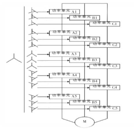
Using cell cascade structure, which consists mainly of software algorithms and network side active inverter motor side vector control algorithm. Unit cascade multi-level voltage inverter, the voltage range of up to 10kV, or even higher; has a very low output harmonics, low torque ripple and motor noise, power factor up to 0.98, each unit is designed completely consistent, easy to replace, so easy to implement redundant design; topology shown below;
2.2Unit main circuit topology
Since no controlled rectifier diode irreversible energy transmission, renewable energy generated on the transmission side of the DC filter capacitor, resulting in pumping voltage. And in GTR, IGBT, represented by full-controlled lower breakdown voltage, high pumping voltage switching devices may be damaged, electrolytic capacitors, and even damage the insulation of the motor, thereby threatening the safety system, which limits the ordinary scope of application of high-voltage inverter; based on energy feedback system solutions to solve the above problems and to achieve a real energy-saving targets rather than wasted energy.
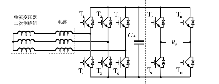
Energy feedback type power unit, a control signal generated by a separate control module, the control module comprises a voltage signal which is sampled in the transformer secondary winding, and the DC link voltage and the inductor current signal, the direct current control unit module by a four-quadrant function and power factor control, the ultimate result of this section is to ensure that the output voltage of the DC bus good static and dynamic performance. The control portion of the inverter side and former Universal voltage inverter consistent, multi-level control of the inverter side by the main chip.
Input isolation transformer secondary windings of a three-phase step-down control signal transmitted via the optical fiber of the IGBT PWM signal control over the conduction on and off via the output means connected in series to the motor. Cell topology diagram is shown below;
2.3Voltage inverter motor vector control to achieve
2.3.1 About inverter motor control algorithm
Master algorithm using high-voltage inverter carrier phase shift control algorithm for voltage overlay, but the core idea of VF or VC algorithm basically follows the low-voltage inverter, inverter at low fields, the software algorithm gone through four generations:
The first generation to U / f = C, sinusoidal pulse width modulation(SPWM) :
High voltage inverter application works: unit cascade mode voltage inverter using carrier phase shift algorithm commonly used as the modulation expected sine wave, triangle wave as the carrier standard, asynchronous / synchronous modulation schemes comparison phase sinusoidal pulse width range of standard output square wave, and other areas of law, to obtain the desired superposition of sine wave; their control principle / control circuit is simple, and in this way asynchronous motor control performance out of the mechanical properties of hardness is better able to meet the general requirements of smooth speed transmission , has such power plants, cement plants, and many other conditions of the fan and pump loads are widely used in various fields. However, this control mode at low frequencies, the output voltage is small, the influence of the stator resistance voltage drop of more significant, therefore resulting in maximum output torque decreases. And its control principle is based on the steady-state equation from the motor, so the dynamic and static torque speed performance are not satisfactory, not suitable for high performance speed control applications.
The second generation of the voltage space vector (flux locus method), also known as SVPWM control.
The third generation in vector control (field oriented method), also known as VC control:
Vector control idea is under a three-phase induction motor stator coordinates alternating current Ia, Ib, Ic, through the three-phase - two-phase transformation, equivalent to a two-phase alternating current Ia1Ib1 stationary coordinate system, and then through the rotor flux directional rotation transformation, equivalent to a direct current Im1 synchronous rotating coordinate system, It1 (Im1 equivalent DC motor excitation current; It1 equivalent torque is proportional to the armature current), then imitate the DC motor control method, DC motor control amount obtained through the corresponding coordinate inverse transform, real-time three-phase sinusoidal output voltage value, the carrier phase shift control algorithm to realize the asynchronous motor control.
The fourth generation of direct torque control, also known as DTC control
1985 German Ruhr University professor Depenbrock first proposed direct torque control theory (Direct Torque Control referred DTC). Direct torque control and vector control is different, it is not to control the torque by controlling the current, flux equal indirect, but the torque is controlled directly as the amount charged.
2.3.2、Vector control algorithm
Its vector control system block diagram of the system:
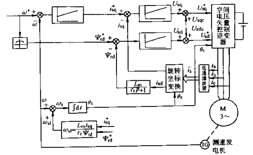
Α-β axis coordinate system in vector control system based on the rotor flux orientation, first the motor phase current is equivalent to two-phase stationary, then converted to the axis of rotation of the DQ coordinate system, then:
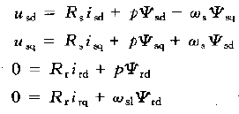
Note:
并So that the D-axis coincides with the direction of the rotor flux, then the Q-axis component of the rotor flux is zero, can be obtained:
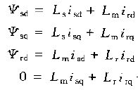
Put this formula into the formula, you can get through simplification:
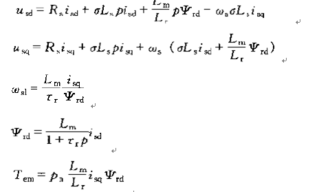
The purpose is to improve the vector control torque control performance, and the final implementation of the stator current is still controlled. By means of the coordinate transformation, so that all the physical transition from a stationary coordinate system to the synchronous rotating coordinate system, standing on the observation synchronously rotating coordinate system, each space vector motors have become stationary vector space vector at each synchronous coordinate system all became straight flow, according to several forms of the torque equation to find the relationship between the various components of the vector between the torque and the accused, real-time control to calculate the torque required for each component of the vector accused value - DC to quantification. Press these to quantitative real-time control, will be able to control a DC motor performance.Since these DC to be quantified does not exist physically , fictional and therefore must be the inverse coordinate transformation process from the rotating coordinate system, the coordinate system back to the rest , the above DC to AC quantitatively converted into actual to quantify the three-phase stator coordinate system to control the amount of exchange , so the actual value is equal to a given value . In the transformation of a vector control method , required to stationary and rotating coordinate system , as well as vector transformation between the coordinate system , AC motor vector control, the motor needs to ABC three-phase stator currents stationary coordinate system Ia, Ib, Ic, converted into α and β two -phase stationary coordinate system (Clarke transformation ) , also called three - phase to two -phase transformation , and from the two -phase stationary coordinate system is converted into synchronous rotating field oriented coordinate system (Park transformation ) , the equivalent DC current Iq synchronous rotating coordinate system , Id (Id equivalent DC motor excitation current ); Iq equivalent torque is proportional to the armature current ) , then imitate DC motor control method , to obtain a DC motor control amount corresponding coordinate through the inverse transform (Park inverse transform ) (Clarke inverse transform ) , to achieve control of the motor.Its essence is the equivalent AC motors DC motors, respectively, for speed, independent control of the two components of the magnetic field. By controlling the rotor flux and the stator current decomposition to obtain the two components of the torque and the magnetic field, through coordinate transformation, achieve orthogonal decoupling control, low frequency high torque capacity.
IDrive vector control four-quadrant inverter can be widely used to enhance the type of load, speed control accuracy and speed for demanding, requiring complex conditions, such as low-frequency large torque, helping users to further enhance the level of process automation, energy conservation, increased more economic benefits.

 Chinese
 English


